When we offer an Office for a day or an hour, we mean that the placement will be given to the client for the time

Renting the comfortable, well-equipped and comfortably furnished Office for an hour, you don't pay the extra money.

The Office is used only when it is actually needed is in the executive order, to organize business meetings, to gather project team.

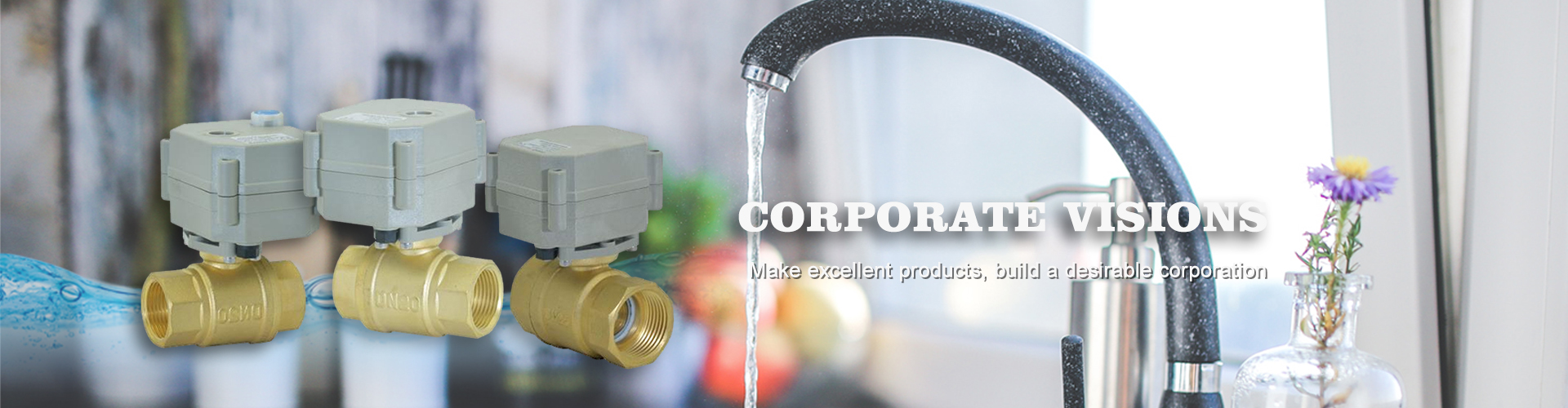
converts industry knowledge and market insight into design-engineered Solutions, which creates competitive advantage for our customers, We call this engineering advantage!
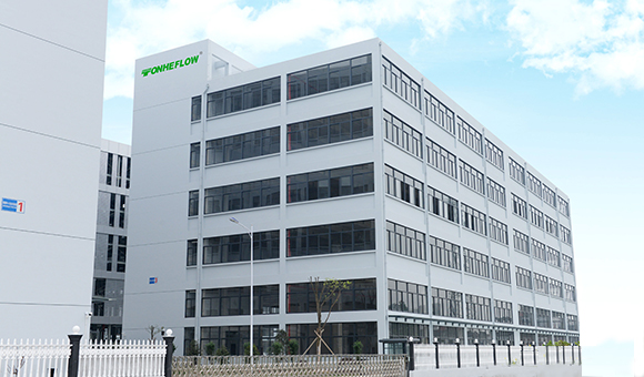
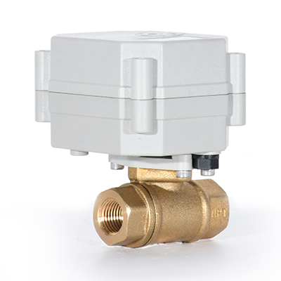
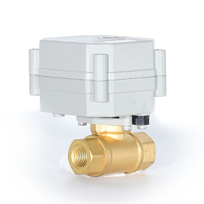
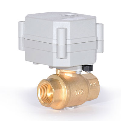
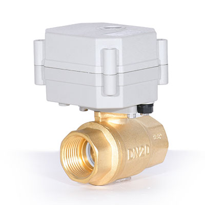
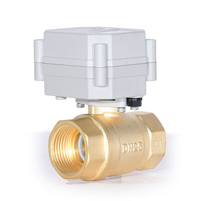
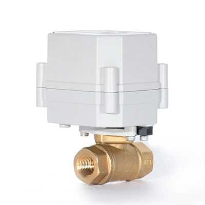
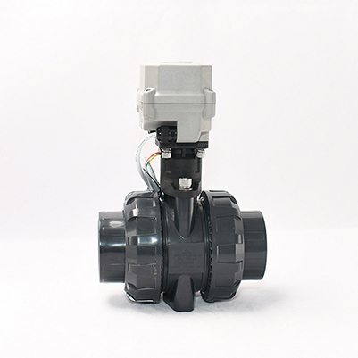
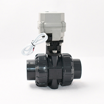
Taizhou Tonhe Flow Control Equipment Co., Ltd. is specialized in the development, design, manufacture, sales and technical service of electric ball valve, electric actuator, wireless leak alarm control system and intelligent fluid control. It is a small and medium-sized scientific and technological innovation enterprise. We mainly produces motorized shut off ball valve from 1/4’’ to 2’’, proportional electric ball valve, intelligent timer controlled valve, household water leakage detection system and other products. Some valves approved NSF61-G, CE, ROHS and other international certification.The motorized valve has compact size with smart shape, Perform reliably, with long life time, intelligent control, high torque actuators, low noise, no leak, and many other features. Which are widely used in air pump tank automatic drainage, automatic watering, water treatment, energy saving, industrial automation and other small equipment .They have broad application prospects, obvious social and economic benefits.
View More